About 175,000 Seabees were staged out of Port Hueneme during the war. Units that had seen extended service in the Pacific were returned to the R&R Center at Camp Parks, Shoemaker, CA. There units were reorganized, re-deployed or decommissioned. Men were given 30-day leaves and later, those eligible were discharged. Informal Units are measurements taken using non-standard units such as hand spans, paperclips, cubes, counters or dominoes. They are used to measure a length and the units have to be either aligned along the length, or one unit has to be repeated and the endpoint of each length marked in some way. For more resources on Measurement for Primary Maths lessons, just go to our dedicated page, that.
What's really the influence of tolerance settings when modeling in Rhino?Change Units In Rhino 8
For investigation I took the default 10 meter long sailboat hull from the Rhinomarine hull modeling module. This is a very clean hull with only few control points as you can see yourself.
The filesize of this hull is 60 kb with Save Small (without render meshes).
Certain operations in Rhino depend on the user tolerance. Examples of geometry build to tolerance are: intersections between two surfaces, section curves, offset curves and surfaces, curves projected onto surfaces. These types of geometry are constructed by refinement methods that stop refining when it is within tolerance. Many other operations build geometry to a much greater accuracy. For instance the intersection of 2 lines that are on the same plane will be much more accurate (thank you Jim).
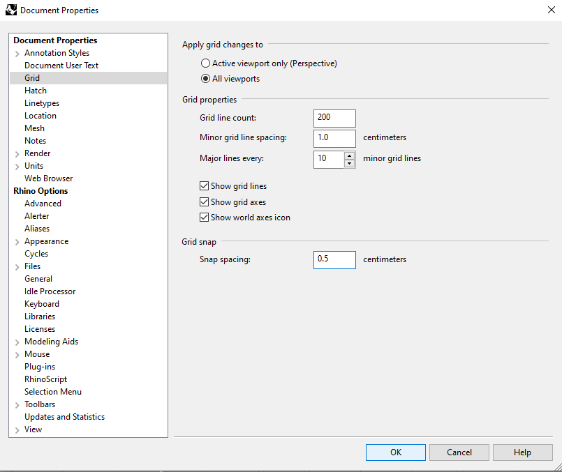
To find and change the tolerance settings open the menu: File/ Properties/ Units. Default values for large objects can be:
- Units: Millimeters
- Absolute Tolerance: 0.01 units (mm)
Then I created two sections:
1- Tolerance set to 1.00 mm. resulted in the red line based on 14 control points
2- Tolerance set to 0.01 mm. resulted in the blue line based on 226 control points
The maximum deviation between the two curves is 0.168406 mm. Find this command under menu: Analye/ Curve/ Deviation
Next I saved each curve including the hull into two separate files which resulted in:
1- 61 kb file for the 1.00 mm. tolerance curve + hull
2- 68 kb file for the 0.01 mm. tolerance curve + hull
The difference in filesize is 10% (Save Small).
After making a frame surface based on the section the difference in filesize is:
1- 66 kb for a single frame surface (+ hull) based on the 1.00 mm. tolerance
2- 103 kb for a single frame surface (+ hull) based on the 0.01 mm. tolerance
The difference increases to 36%.
At last a solid frame is made with a certain thickness which increases the filesize even more:
1- 80 kb for a single solid frame and hull (1.00 mm. tolerance).
2- 174 kb for a single solid frame and hull (0.01 mm. tolerance).
Resulting in a more than 2 times bigger file for the 0.01 mm. tolerance frame.
Why not model in centimeter or meters?
This is worth considering but as millimeters is the standard in a lot of industries, most people think in mill and AutoCAD drawings are also often in mm. Even with large products like ships and architecture I found out it is confusing to start modeling in meters and scale Acad drawings for input over and over again.
 My conclusions are:
- tolerance settings can have a big impact to file size
Change Units In Rhino Pro
- the impact gets bigger if 3d models are detailed up to solids

- deviation between the two analysed situations is a very little 0.168406 mm
Recommendation:
 - depending on manufacturing techniques and accuracies, 0.5 or 1mm. absolute tolerance seems to be worth to consider with large and detailed 3d models such as ships, yachts and architecture
Some related commands:
- Rebuild; investigate the amount of control points and rebuild curves with less control points
- FitCrv; fit a curve to certain tolerance to the original object
- CrvDeviation; to measure the maximum deviation between two curves
You can download the file yourself over here